Contactors: Functions and Components Explained
A contactor is an electromagnetic device that is used for switching an electrical power circuit on or off. It is a multi-pole switch i.e. multiple power circuits can be controlled by a single contactor. As it is controlled by electromagnetism, we don’t have to switch on or switch off it manually.
A Contactor is considered to be a special type of relay. However, the general difference between the relay and contactor is that the contactor is employed in applications with higher current carrying capacity (up to 12500 A), whereas the relay is employed for lower current applications. Contactors are compact in size and are often field-mounted easily. These electrical devices feature multiple contacts in general. In most cases when the contactor coil is energized these contactors remain open and provide operating power to the load. Contactors are generally used for controlling electric motors.
There are various sorts of contactors, and all of them have their own set of features, capabilities, and applications. Generally, the current breaking capacity of a contactor ranges from a few amperes to thousands of amperes, and the voltage breaking capacity ranges from 24 VDC to thousands of volts. Contactors also come in varying sizes, from hand-held dimensions to sizes measuring a meter or yard on one side (approximately).
These devices are mostly used in the application of high-current load as they can handle currents of over 5000 amperes and high power over 100 kW. They can also reduce and control the generation of arcs due to heavy motor currents when being interrupted.
Contactor – Design and Construction
The basic construction of a contactor is almost the same as a relay. It consists of the following parts-
- Contact: This is one of the important parts of contactor. The current carrying task of the contactor is completed by the contacts. There are various types of contacts present in a contactor namely, contact springs, auxiliary contacts, and power contacts. Each of them has their own individual role to play.
- Electromagnet: This is the most vital component of a contactor. It provides the driving force that is required to close the contacts of the contactor.
- Enclosure: The enclosure provides insulation and protection from personnel touching the contacts. Both the coil or electromagnet and contacts are protected by an enclosure. These protective enclosures are made from various materials, such as polycarbonate, polyester, Nylon 6, Bakelite, thermosetting plastics, etc. Generally, the open-frame contactor has an additional enclosure, which protects the device from bad weather, hazards of explosion, dust, and oil.
- Arc Suppressor: One of the key functionalities of a contactor is the arc excitation. AC arcs are often easily extinguished since it passes through zero twice for each cycle. Hence arc suppressors can do the job easily. But for DC arcs, magnetic blowouts or specially designed arc chutes for arc extinction are necessary. Depending on the application, different arc suppression arrangements are made in contactors out of which arc chutes are one among them.
- Economizer circuit: An economizer circuit is the one used to reduce the power consumed by the coil. During pickup the economizer circuit supplies a high current and later it supplies adequate power to stay the contacts closed. It is not mandatory that each one of them must have an economizer circuit.
The contact a part of the contactor includes the facility contacts also because the auxiliary contacts. The power contacts gain the power for the contactor and the auxiliary contacts is used to bring a loop with the rest of the rest of the devices it is attached to. These contacts are connected to the contact springs.
The electromagnets control the contacts of the contactor. These electromagnets give the initial force to the contacts and make them closed. Both the contacts and electromagnet are enclosed in a frame. The frame is usually made of insulating materials. The insulating material that is used completely insulates the contacts and helps in preventing the touch of contacts. For high-end contactors, an open-frame contactor is commonly used to provide greater protection from oil, dust, weather, and also from an explosion. According to the required voltage rating, the type of frame housing used may also differ. If the contactors are used to manage volts higher than 1000 volts, inert gases and also vacuum is used as frame housing.
How the Contactor Operates
Operating Principle of a Contactor: When current passes through the contactor it excites the electromagnet or coil and an electromagnetic field is produced due to the excitation. The magnetic field, helps the contactor core to move the armature. The circuit between the fixed contacts and the moving contacts is completed by a normally closed (NC) contact. This allows the current to flow through these contacts to the load. When current is removed, de-energization occurs in the coil and it opens the circuit. The rapid open and close action of the contactor is one of its important features.
Working of Contactor
Contactors are used for high-current load applications. They are specifically designed to control and reduce the arc produced when the heavy motor currents are interrupted. Other than the low current contacts, they are also set up with NC(normally closed) contacts. They can handle more than 20 Amperes current and over 100 KiloWatts power.
The contactor has an AC/DC supply-driven coil input which depends on the requirement. Generally, a lower voltage PLC will control the coil of the contactor. Sometimes motor voltage may also control the coil. The motor may have series of coils connected to either control the acceleration or even the resistance.
When a high current is passed through the contactor, the electromagnet starts to build up and produces magnetic flux. Hence, the core of the contactor starts to wind up. This process helps in energizing the moving contact. Thus, the moving and fixed contacts make a short circuit and the current is passed through them to the next circuit. The electromagnetic coil draws more current initially. But this reduces as soon as the metal core enters the coil. When the current is removed, the coil gets de-energized and thus the contacts get open circuited.
Contactor Ratings
Ratings of a contactor are given according to the pole of the contactor. It also depends on factors like fault withstand current, coil voltage and so on. According to their rating, contactors are classified into the following.
- AC1 – Non-inductive rows
- AC2 – Contactors for starting of slip-ring motors
- AC3 – Starting of squirrel-cage motors and switching off only after the motor is up to speed.
- AC4 – Starting of squirrel-cage motors with inching and plugging duty.
- AC11 – Auxiliary control circuits
Wide Band AC/DC operated Coil Voltages
Wideband coils ranging from 100V to 250V are available and electronic coils ranging from 24V to 60V are available.
These products are available for all applications including wind, solar, starter panel, UPS, traction, EV, safety contactors, and more.
The main advantage of using wideband coils is that the inventory costs can be significantly reduced.
The Coils of a contactor can be energized by below voltage ratings in AC/DC,
In AC -24V, 110V, 220-230V and 400-415V
In DC – 20-60V, 48-130V, 100-250V, 250-500V and 77-143V
AC And DC Contactors
Contactors can also be classified as AC and DC contactors.
- AC Contactors
AC contactors work on the principle of electromagnetic attraction. They have a shading coil which is a metallic ring with high remanence which provides magnetism during the zero crossing of AC voltage. The presence of the shading coil in AC contactors can result in higher drop-off voltage which can cause delay in contact operation. - DC Contactor
DC contactors also work on the principle of electromagnetic attraction. But they do not have any shading coils. Hence, if a DC coil is powered with AC voltage, the contactor can chatter as the magnetism becomes zero during the zero crossing of the AC voltage. It can produce an audible noise and can cause contact to change state and lead to malfunction or unwanted interruption in the circuit.
Types of Contactor.
- Auxiliary Contactor.
- Power contactor:
- ESB and EN Installation contactors.
- Mini contactors
- Vacuum Contactor.
Power Contactors
Power contactors are usually used as the main contactors. They can handle loads of about 600A. They are generally used in power circuits to get on /off control for the operation of the machines, motors, and any other electrical equipment.
Auxiliary Contactor
An auxiliary contactor is basically a regular (low-power) relay but built like a “power” contactor and when used together with another contactor it is called an auxiliary contactor. It is used to connect or disconnect the circuit i.e. to control power contactors. Auxiliary contactors usually have auxiliary contacts only and they do not have any main contacts. They can handle loads up to 6A only.
ESB and EN Installation Contactors
ABB’s hum-free installation contactor designs offer a wide range of ratings from 16 A to 100 A. It is widely used in buildings for switching and controlling lighting, heating, ventilation, motor, and pumps. The installation contactors take noise reduction to a new level. An innovative AC/DC design helps in eliminating hum and to select the tool-free accessories as well as manual and automatic versions. They also offer peace of mind in noise-sensitive applications.
Mini Contactors
Mini contactors from ABB are ideally suited for applications where space is at a premium. As they are the flattest on market, therefore they can be used in special modular and compact applications. The small dimensions, a wide range of coil supplies and a variety of versions within the model range provide customers with high flexibility in use for applications up to 20 A resistive loads and motor loads up to 5.5 kW.
Vacuum Contactor
V-Contact VSCs are suitable for controlling electrical apparatus in industry, the service sector, the marine sector, etc. As it uses vacuum interrupters for breaking the contacts, therefore it can be operated in difficult environments particularly. The various application of vacuum contactor includes the control and protection of motors, transformers, power factor correction banks, switching systems, etc.
Features of Contactors
- A contactor is a relay that is used for switching power.
- They usually handle very heavy loads like an electric motor, lighting and heating equipment and, so on.
- Contactors are controlled by a circuit with very less power even though their output is used for switching very high loads.
- They can vary in size from a small device to as huge as a yard depending on the loads they have to handle.
- Like circuit breakers, they do not interrupt a short-circuit current.
- Their current and voltage breaking capacity range from a few amperes and 24 DC volts to thousands of amperes with many kilo volts respectively.
Advantages of Contactors:
- Speed-up your projects: Simpler selection process
- Easy to install: Faster fitting by design
- Continuous operation: Proven, secure, trusted
- Save time
- Environmentally sound
- Safe and reliable control circuits
- Protect control circuits and save space
- Switching operation is very fast
- By using a single contactor switch we can control multiple circuits
- It can work for both AC and DC devices
- Construction of a contactor is quite simple
Disadvantages of Contactors
- Coil of the contactor may burn in absence of magnetic-field. As a result the contacts won’t close and the contactor will not function properly.
- Contacts may also weld shut which may cause the load to keep running even when there is no control voltage which may cause unsafe machine or machine damage.
Difference Between a Relay and a Contactor
| SL. NO. | RELAY | CONTACTOR |
| 1. | Relays are primarily used on low voltage, low amperage circuits. | Contactors are used to power up larger loads such as induction motors. |
| 2. | A Relay is similar to an auxiliary contactor, which is generally used in control circuits. | Contactors can be classified as -power contactors and auxiliary contactors. |
| 3. | The size of a relay is comparatively small. | The size of a contactor is larger than a relay. |
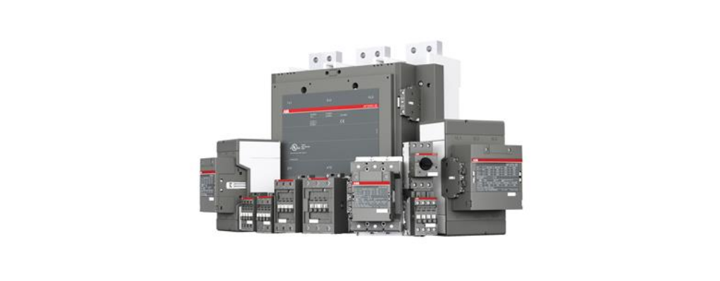
ABB Contactors are known for their quality and reliability. We are the leading online suppliers and distributors for ABB Contactors.
Visit www.micronovaimpex.com, the leading online electrical product supplier and distributor. To shop for the best quality Contactor from ABB, reach us at digitalsales@micronovaimpex.com or call us on +91 8147090154
Comment (1)
Thank for the detail explanation on different types of contactors